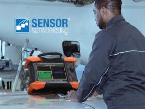
Inspection of critical assets in the oil and gas and power generation industries may be necessary, or advantageous during normal plant operations. Despite the advantages of such testing, on-stream inspections remain a challenge for energy producers and testing service providers. Due to the high temperatures some assets reach, current solutions are cumbersome, expensive, or altogether untenable.
To inspect high-temperature assets, the team at Sensor Networks Inc. created a line of phased-array and time-of-flight diffraction (TOFD) transducers and corresponding wedges. The main goal of the testing and validation of these products was to provide industries with cost-effective, reliable, and convenient alternatives that covered a wide range of inspection temperatures.
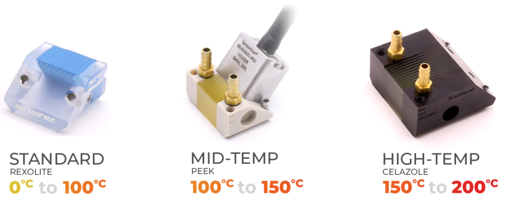
To establish a high-temperature wedge, SNI first had to choose which material(s) would satisfy the necessary requirements. Three parameters were important when assessing materials. The first parameter was the wedge material velocity at a given temperature. The wedge material’s velocity drives the incident angle of the wedge for a given application. If an inspection is done at 150°C (302°F), the velocity change in the wedge material selected must be accounted for. Each material has a different coefficient of thermal expansion (CTE) and will be susceptible to decreases in velocity. As temperature changes, adjustments may need to be made to the instrumentation calibration to ensure accurate data is being collected. This relationship is driven by Snell’s Law which is defined as 𝑠𝑖𝑛(𝜎1)/𝑉1 = 𝑠𝑖𝑛(𝜎2)/𝑉2. If the velocity changes in the wedge material, the incident, and refracted angles will change and there may be a need to cut a different incident angle on the wedge and adjust the calibration process.
To show the relationship between temperature and instrument calibration, samples of a set dimension were first placed in an oven that was set to 200°C (392°F). Next, measurements of material velocity were taken before the samples were put into the oven, once they reached room temperature, and then at 25°C (45°F) intervals until the temperatures reached the 200°C (392°F) level. Figure 9 illustrates the percentage of velocity change across this range.
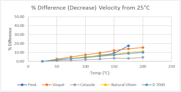
Figure 9: Percentage Change Velocity from 25° to 200°C
The second factor considered when designing the wedges was the acoustic sensitivity that the transducer could maintain across various temperature ranges. One of the biggest difficulties engineers experienced when designing high-temperature transducers is that as the temperature of the transducer climbs, there can be a degradation of the acoustic performance. Degradation of acoustic performance can occur because wedge material becomes more attenuative at higher temperatures. If the wedge becomes too attenuative at elevated temperatures and begins to require more energy to perform a given inspection, the signal response may degrade to the point where it is unusable. Figure 10 illustrates the difference in gain necessary to achieve 80 percent of full-screen height as the temperature changes.
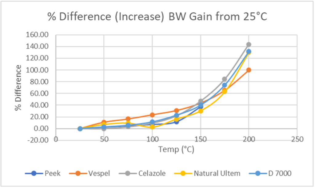
Figure 10: Percentage Change in Bandwidth from 25° to 200°C
The third focus of SNI Engineers when designing the high-temp wedge was ensuring that the wedge material did not begin to filter out high-frequency components of the UT signal. Many inspections in the oil and gas and power generation segments require a 5 MHz or higher transducer to accurately identify and size defects within an asset. Knowing the type of defect, size, and location are all important in maintenance decisions. Figure 11 illustrates data outlining those changes. This graph represents a decrease in center frequency across the temperature range of the probe. Notice that Celazole² is the only material able to maintain the center frequency. While this is what the test result at the time yielded, this result has not been replicated. Expected results would be signals that yielded a 20 – 35 percent difference from room temperature.
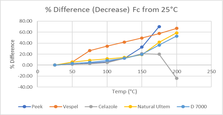
Figure 11: Percentage Decrease in Center Frequency Across Temperature Range
After conducting the research outlined above, SNI engineers began to solidify their selection of materials for two high-temp wedges: a solution to inspect a medium temperature range of 100°C-150°C (212°F-302°F) and a solution to inspect a high-temperature range of 150°C-200°C (302°F-392°F). From the data collected, Peek³ was selected for the 100°-150°C inspection range and Celazole for the 150°C-200°C range. As the experiment concluded, further testing was done to establish a normalization period so engineers could account for the change in material velocity that would impact the refracted angles in the inspection piece. Ensuring that the temperature of all parts involved is as stable as possible before starting a calibration is critical.
Blocks sized 25.4mm x 25.4mm x 50.8mm (1” x 1” x 2”) of each material were machined with holes drilled at 6.35mm (0.25”) intervals. Thermocouples were then potted inside the block so an accurate temperature gradient could be established in the material. Each block was then placed on a hot plate set at 200°C (392°F) and monitored in 5-minute intervals for an hour. Temperatures were checked at each level to normalize the time it takes to achieve stability in each material analyzed. The data that was collected for each material has been listed below in Figure 12. Note that the normalization for the Peek material is approximately 30-35 minutes and the normalization period for Celazole is approximately 40 minutes.
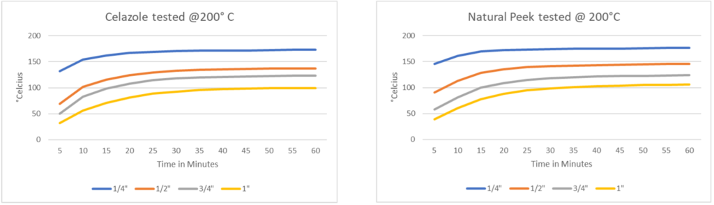
Figure 12: Natural Peek, Celazole Temperature Gradient
Current solutions for inspections at elevated temperatures are limited. This new wedge solution has created a versatile and cost-effective, off-the-shelf solution for inspection service providers and asset owners. The assets being inspected are of high value to their owners, to the overall safety of the people working on them, and to the environment. Safe and effective on-stream inspection of these systems is vital to their continued reliable operation and for improved outage planning.
To see how SNI designed its line of high-temp transducers, click here. For a more in-depth look at the high-temperature options available with SNI, view our brochure.
Sensor Networks Inc. (SNI) is a U.S.-based technology company that specializes in Non-destructive testing (NDT). With dozens of experts and over a hundred years of combined NDT experience, SNI helps customers inspect their assets safely and cost-effectively. SNI has a hands-on approach and individualizes every customer experience.
Notes:
- 1. The only material not tested across the full range was Peek. The velocity decrease after the temperature reaches 150°C (302°F) makes the material unusable in applications over that temperature range.
- 2. Celazole PBI is the highest performance engineering plastic available today. It offers the highest heat resistance and mechanical property retention over 400°F (205°C) of any unfilled plastics. It has better wear resistance and load carrying capabilities at extreme temperatures than any other reinforced or unreinforced engineering plastic.
- 3. Polyetheretherketone: PEEK material (polyetheretherketone) is a high-performance semi-crystalline engineering thermoplastic with outstanding harsh chemical resistance, very low moisture uptake, good fire performance, excellent mechanical strength across a broad temperature range, and good dimensional stability.