Inspection of critical assets in the oil and gas and power generation industries may be necessary, or advantageous during normal plant operations. Despite the advantages of such testing, on-stream inspections remain a challenge for energy producers and testing service providers. Due to the high temperatures some assets reach, current solutions are cumbersome, expensive, or altogether untenable. To inspect high-temperature assets, the team at Sensor Networks Inc. created a line of phased-array and time-of-flight diffraction (TOFD) transducers and corresponding wedges. The main goal of the testing and validation of these products was to provide industries with cost-effective, reliable, and convenient alternatives that covered a wider range of inspection temperatures than previous inspection options.
In the development of SNI’s new line of high-temperature inspection devices, the primary goal was to design and produce TOFD and phased-array transducers that could withstand prolonged exposure at elevated temperatures. As testing progressed, a secondary goal was established: to ensure all transducers would have the same performance as their standard-temperature equivalents.
As the team navigated the design process, multiple stages of product testing were conducted. The biggest issue in the testing process was the drop in sensitivity that occurred when temperatures increased. To understand the limitations of a standard transducer, a comparative study was conducted. Figures 1 and 2 show before and after photos of identical inspections, the first taken at room temperature and the second at 204°C (400°F). Before capturing Figure 2, there was a fifteen-minute normalization period. This allowed the wedge and transducer to get up to temperature.
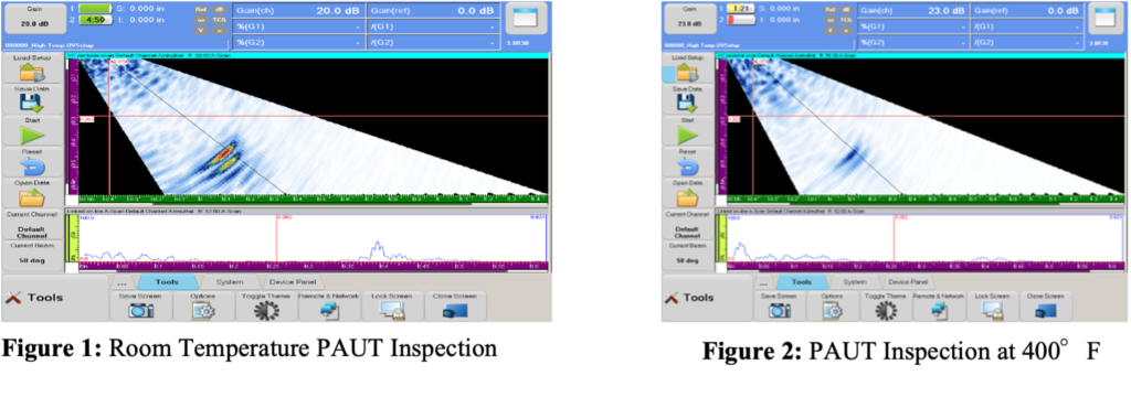
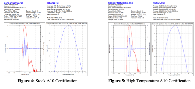
With 3 decibels (dB) of additional gain, the same defect in the part can be seen at room temperature, and at elevated temperature, thus ensuring any sensitivity is not lost which was important to the success of the project and the new design. Figures 4 and 5 show comparisons in the standard 16-element A10 model transducer, and the equivalent high-temperature A10 design. The waveforms are very similar and the average sensitivity over all 16 elements in the array, is < 2dB.
After it was ensured that the sensitivity specification was met, the focus shifted to the mechanical design of the transducer. The coefficient of thermal expansion (CTE) was a major consideration for all materials needed to build the transducer. CTE causes expansion in materials as their temperature increase and cool down. Understanding how each material behaves with the other is important. The stress created during expansion can damage the transducer, especially over time.
To ensure that the transducer would survive repeated stresses, a fixture was machined and attached to an actuating arm. The apparatus was then placed over a small kiln that had an opening on the top. The actuator was wired to a microcontroller to control when it was raised and lowered. A complete cycle was set at twenty minutes, fifteen minutes in the kiln, and five minutes out. A goal of one hundred cycles at 200°C (392°F) was established to validate that transducer would survive extended use at 200°C (392°F). Figure 6 shows the complete testing setup.
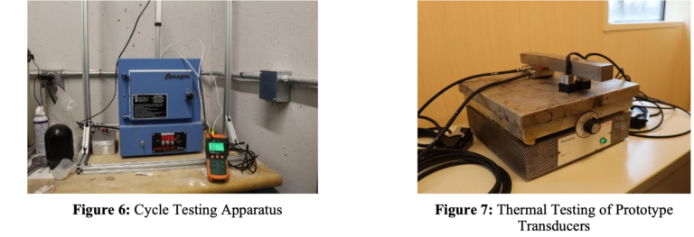
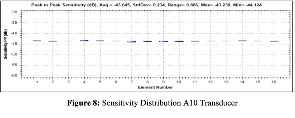
Along with the temperature cycling requirement, a requirement for time was established. One hundred total hours exposed to a temperature of 200°C (392°F) was the target. This testing also needed to be as close to “live” as possible in a lab environment. To achieve this, all prototype transducers were placed on a hot plate set to and measured at 200°C (392°F). Delay lines were machined to be attached to the bottom of the phased-array transducers to simulate the actual distance from the heat source they would experience in the field. The corrosion arrays were simply placed directly on the hot plate, much like they would be while in service. After 100 hours on the heat source, all the probes were removed and re-certified using a standard process and procedure. Figure 7 shows the probes undergoing testing on the heat source. Figure 8 shows the sensitivity distribution of all the elements in the same 16-element A10 transducer that was shown above. This chart represents the performance of each element after exposure to temperature testing. The performance is still well within the requirements established for standard probes.
As outlined above, Sensor Networks went through rigorous testing procedures to ensure that the best design was chosen for its high-temperature transducers. To see how SNI designed its corresponding high-temp wedges, click here. For a more in-depth look at the high-temperature options available with SNI, view our brochure.
Sensor Networks Inc. (SNI) is a U.S.-based technology company that specializes in Non-destructive testing (NDT). With dozens of experts and over a hundred years of combined NDT experience, SNI helps customers inspect their assets safely and cost-effectively. SNI has a hands-on approach and individualizes every customer experience.