I1
Immersion Transducers
Part Numbers
| Frequency (MHz) | Element Diameter | Focus | Part Number | ||||
|---|---|---|---|---|---|---|---|
| inch | mm | GP* | HR* | C* | Accessories | ||
| 2.25 | 0.25 | 6.4 | None | 00-011300 NF | 00-011301 NF | 00-011302 NF | |
| Spherical | 00-011300 X.XS | 00-011301 X.XS | 00-011302 X.XS | ||||
| Cylindrical | 00-011300 Y.YC | 00-011301 Y.YC | 00-011302 Y.YC | ||||
| 5 | 0.25 | 6.4 | None | 00-011303 NF | 00-010593 NF | 00-010711 NF | |
| Spherical | 00-011303 X.XS | 00-010593 X.XS | 00-010711 X.XS | Cable | |||
| Cylindrical | 00-011303 Y.YC | 00-010593 Y.YC | 00-010711 Y.YC | MD – BNC | |||
| 10 | 0.25 | 6.4 | None | 00-010822 NF | 00-010377 NF | 00-010823 NF | 6-ft (1.83 m) |
| Spherical | 00-010822 X.XS | 00-010377 X.XS | 00-010823 X.XS | 07-010012 | |||
| Cylindrical | 00-010822 Y.YC | 00-010377 Y.YC | 00-010823 Y.YC | ||||
| 15 | 0.25 | 6.4 | None | 00-010596 NF | 00-011304 NF | ||
| Spherical | 00-010596 X.XS | 00-011304 X.XS | |||||
| Cylindrical | 00-010596 Y.YC | 00-011304 Y.YC |
Case Dimensions
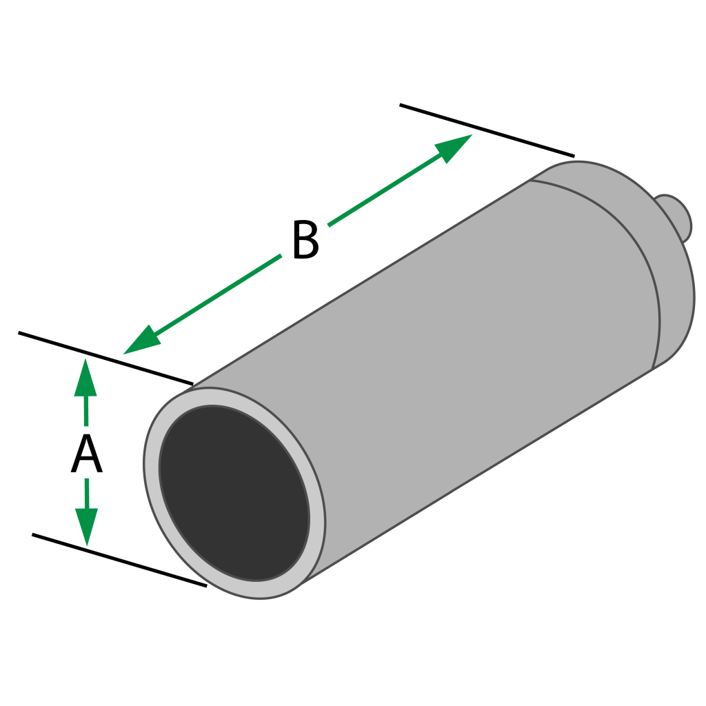
| Element Diameter | A | B | |||
|---|---|---|---|---|---|
| inch | mm | ||||
| 0.25 | 6.4 | 0.38 in. | 9.7 mm | 1.25 in. | 31.8 mm |
To specify the Focal Length (in inches) and Focal Type (spherical or cylindrical) you desire: Edit the X.XS and Y.YC suffixes shown in the chart to match your requirements. (ex. The suffix for a 2.0″ spherical focus is changed from X.XS to 2.0S; the suffix for a 3.0″ cylindrical focus is changed from Y.YC to 3.0C)
NF = Non-focused (flat); S = Spherical focus; C = Cylindrical focus
| Frequency (MHz) | Element Ø (Inches) | |||||
|---|---|---|---|---|---|---|
| 1 | 0.75 | 0.5 | 0.375 | 0.25 | ||
| 1 | Near | 4.3 | 2.4 | 1.1 | ||
| Min | 2.0 | 1.5 | 0.75 (2) | |||
| Max | 2.75 | 1.75 | 0.75 (2) | |||
| 2.25 | Near | 9.6 | 5.4 | 2.4 | 1.4 | 0.6 |
| Min | 2.0 | 1.5 | 1.0 | 0.75 | 0.375 (2, 3) | |
| Max | 6.0 | 3.5 | 1.5 | 1.0 | 0.375 (2, 3) | |
| 3.5 | Near | 15.0 | 8.4 | 3.7 | 2.1 | 0.9 |
| Min | 2.0 | 1.5 | 1.0 | 0.75 | 0.375 (3) | |
| Max | 8.0 | 5.5 | 2.25 | 1.25 | 0.5 | |
| 5 | Near | 21.0 | 12.0 | 5.4 | 3.0 | 1.3 |
| Min | 2.0 | 1.5 | 1.0 | 0.75 | 0.5 | |
| Max | 8.0 (1) | 7.5 | 3.5 | 2.0 | 0.75 | |
| 10 | Near | 24.0 | 10.7 | 6.0 | 2.7 | |
| Min | 1.5 | 1.0 | 0.75 | 0.5 | ||
| Max | 8.0 (1) | 6.0 | 4.0 | 1.5 | ||
| 15 | Near | 16.0 | 9.0 | 4.0 | ||
| Min | 1.0 | 0.75 | 0.5 | |||
| Max | 6.0 (1) | 5.0 | 2.0 |
Near = Nearfield length in water; Min = Minimum recommended focal length in water; Max = Maximum recommended focal length in water
All focal lengths are listed in inches of water from the reflection off a flat stainless steel reflector. Divide by 4 for the approximate distance in steel.
Focal lengths are offered in 0.35″ increments between the Min. and Max listed. Focal lengths outside the recommended limits can be ordered, but on a best effort bases only.
1 – Achievable focal lengths of these models are shorter compared to their near field length due to attenuation and other effects at long water paths. Longer focal lengths can be ordered, but on a best effort basis.
2 – Max and Min. focal lengths are the same for these models due to the physics and geometry of this combination.
3- A focal length other than the normal 0.25″ increment is offered in this combination.
Please confirm your focal length in your applications: Use of probes with F-Numbers under 4.0 (near the minimum focal length listed on this chart) can introduce other wave modes and/or be less effective since acoustic energy at the edge of the beam may be at relatively high incident angles. F-Number = Focal Length/Element Diameter. (ex. 2.0″ focus probe with 0.375″ element = 2.0″/0.375″ = F-Number = 5.3)
I1 Immersion Transducers
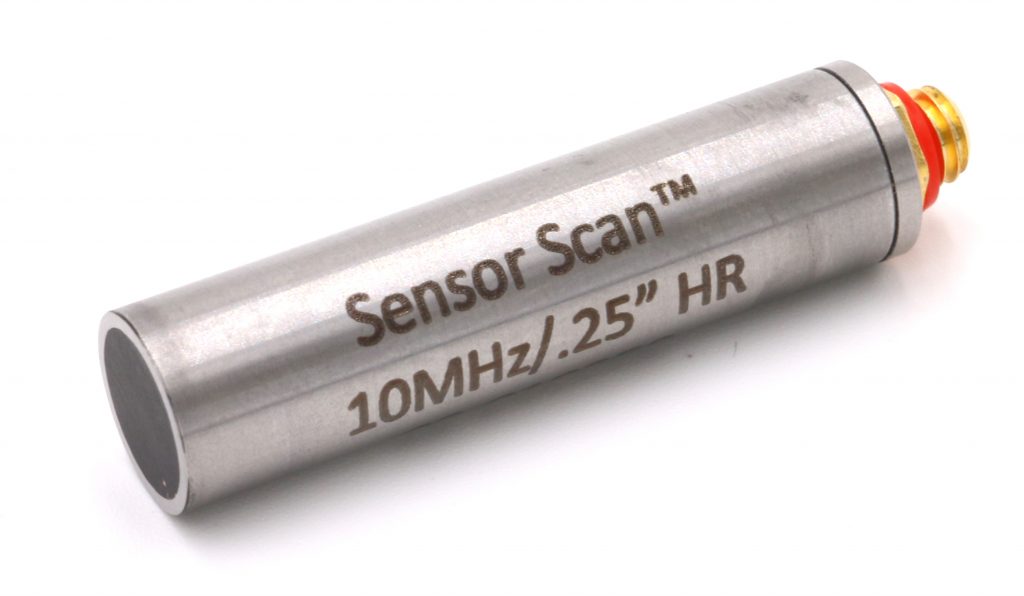
Model I1 are small-diameter, pencil-type transducers with straight-mounted Microdot connectors. Because the connectors are not waterproof, sealing with non-water-soluble grease is recommended. GP series* offer the best combination of sensitivity and resolution for general applications. HR series* are highly damped for applications where high resolution is required. C series* have piezocomposite elements and offer superior penetration, resolution, and signal-to-noise ratio in highly-attenuative and coarse-grain materials.
Immersion transducers are typically used in automated and manual-scanning systems using water or other liquid as a coupling medium. This enables the inspection of parts with complex geometries and near-surface resolution superior to that of contact transducers. Spherical (point) or cylindrical (line) focusing can further improve sensitivity and resolution. Focal length and focal type must be specified. See Focal Length & Type for more information.
Typical Applications
- Inspection of complex geometries
Series
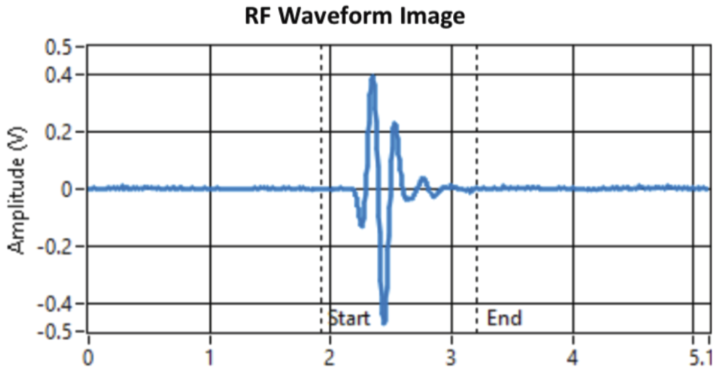
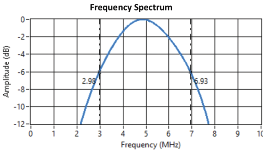
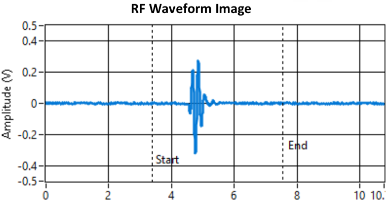
*GP Series – General Purpose series of transducers are recommended for most applications and have a good trade-off between sensitivity and resolution. They have a medium frequency bandwidth of 40-65% at -6db but with more ring-down cycles in the waveform.
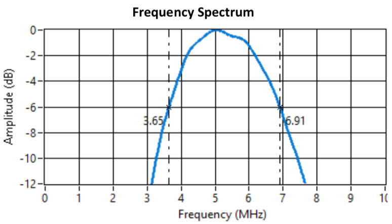
*HR Series – High Resolution series of transducers are highly damped and recommended for applications where enhanced axial and near-surface resolution are more important. Generally includes thickness measurement and near-surface flaw detection. HR series have less sensitivity and the GP or C series with -6db frequency bandwidth of 50-100% range.
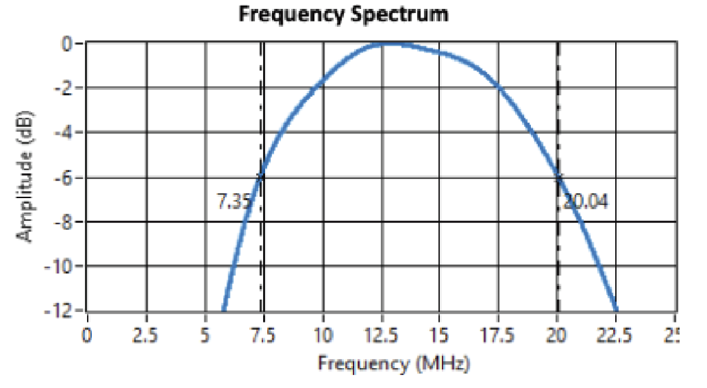
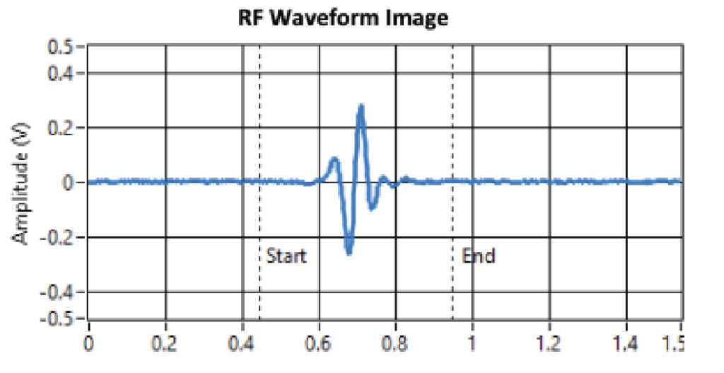
*C Series – Composite (Piezocomposite) series of transducers have superior sensitivity and penetration, especially in highly-attenuative materials. C Series have both higher resolution, sensitivity, and have wide bandwidth (60-120% at -6db) due to the lower acoustic impedance of the material. They couple more efficiently into plastic wedges, delay lines, and water.
