WELD INSPECTION
Phased arrays and wedges

Array Transducers
Wedges
Technology & Features
Resources
Array Transducers
Part Numbers
| Case | Frequency (MHz) | Number of Elements | Element Pitch | Element Elevation | Part Number | ||
|---|---|---|---|---|---|---|---|
| Inch | mm | Inch | mm | GP* | |||
| A4 | 0.5 | 16 | 0.110 | 2.80 | 1.02 | 26 | 00-011821 |
| 1.5 | 16 | 0.110 | 2.80 | 1.02 | 26 | 00-011416 | |
| 2.25 | 16 | 0.080 | 2.00 | 1.26 | 32 | 00-011417 | |
| A5 | 2.25 | 32 | 0.030 | 0.75 | 0.94 | 24 | 00-011418 |
| 5 | 32 | 0.024 | 0.60 | 0.76 | 20 | 00-011424 | |
| A31 | 5 | 32 | 0.024 | 0.60 | 0.39 | 10 | 00-011925 |
| 7.5 | 32 | 0.024 | 0.60 | 0.39 | 10 | 00-012621 | |
| 10 | 32 | 0.024 | 0.60 | 0.39 | 10 | 00-013043 | |
| A32 | 5 | 32 | 0.040 | 1.00 | 0.39 | 10 | 00-011839 |
| 5 | 64 | 0.020 | 0.50 | 0.39 | 10 | 00-011503 | |
| 10 | 64 | 0.020 | 0.50 | 0.39 | 10 | 00-011924 | |
| AWS | 2.25 | 16 | 0.040 | 1.00 | 0.63 | 16 | 00-010477 |
| E1 | 2 | 8 | 0.040 | 1.00 | 0.35 | 9 | 00-010274 |
Case Dimensions
| Case Type | Case Dimensions | |||||
|---|---|---|---|---|---|---|
| Length | Width | Height | ||||
| A4 | 2.24 in. | 56.9 mm | 1.81 in. | 46 mm | 1.18 in. | 30 mm |
| A5 | 1.14 in. | 29 mm | 1.69 in. | 42.9 mm | 0.94 in. | 23.9 mm |
| A31 | 1.20 in. | 30.5 mm | 1.10 in. | 27.9 mm | 0.98 in. | 24.9 mm |
| A32 | 1.58 in. | 40.1 mm | 1.10 in. | 27.9 mm | 1.0 in. | 25.4 mm |
| AWS | 1.26 in. | 32 mm | 0.80 in. | 20.3 mm | 0.75 in. | 19 mm |
| E1 | 1.1 in. | 27.9 mm | 0.59 in. | 15 mm | 1.06 in. | 26.9 mm |

Wedges
| Case | Description | Part Number | Dimensions | |||||
|---|---|---|---|---|---|---|---|---|
| Length | Width | Height | ||||||
| A4 | 30-70 Shear | 01-011744 | 1.14 in. | 29 mm | 1.18 in. | 30 mm | 0.79 in. | 20 mm |
| A5 | 30-70 Shear | 01-011746 | 1.20 in. | 30.5 mm | 1.58 in. | 40.1 mm | 0.64 in. | 16.3 mm |
| A31 | 0 Degree Delay, 20mm | 01-010943 | 2.56 in. | 65 mm | 1.18 in. | 40 mm | 0.79 in. | 20 mm |
| N55S (30-70 Shear), porting, wear pins, 8mm gimbal holes | 01-010943-P | 2.70 in. | 68.6 mm | 1.58 in. | 40.1 mm | 1.70 in. | 43.2 mm | |
| A32 | 0 Degree Delay, 20mm | 01-011554 | 0.98 in. | 24.9 mm | 0.91 in. | 23.1 mm | 0.79 in. | 20 mm |
Technology & Features
Weld Inspection Arrays
Weld inspection arrays paired with the right phased-array wedge are perfect for conducting inspections on various weld, plate, and forging applications. Various options for arrays and wedges offer the ability to meet and optimize inspection requirements. Custom array and wedge options are available upon request.
Typical Applications
- Inspection for a wide range of weld applications
About Linear Arrays
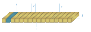
The linear array is the most common form factor used in industrial phased array testing including TFM/FMC applications. The linear array allows electronic control of the active plane of the transducer including steering angle, depth of focus, and position of the sound beam.

- A single element in the array. In this graphic, 1 of 16 elements.
- Width of a single element.
- Space between adjacent elements.
- Array Pitch; the distance between the center points of two adjacent elements. Pitch controls the arrays resolution and steering ability.
- Array Elevation; the length of the elements.
Resources


